To establish a rigorous, multi-scale empirical baseline for the "inverse-sandwich" EPSB-RC system. Data extracted here feeds directly into the Total Strain Based Crack Model (TSBCM) for DIANA NLFEA validation.
CONSTITUTIVE LEVEL (MATERIAL)
Exacting standard mechanical properties of the EPS formwork.
Fracture mechanics and time-dependent shrinkage of C30/37 SCC.
Anisotropic compressive validation and Weibull variance of GFRP.
MESO-SCALE LEVEL (TOPOLOGY)
Empirically validating the Interface Integrity Constraint ($\tau_{int,eff} \le \tau_{Rd}$).
Proving the EPS formwork supplies passive lateral confinement ($f_{cc}$) to suppress premature nodal web crippling.
Apparent density ($\rho_a$) fundamentally governs the compressive stiffness and thermal conductivity of the EPS formwork. It serves as the primary QA/QC metric for material homogeneity.
SETUP SUMMARY
Dimensions: $200 \times 200 \times 75$ mm (Right-angled parallelepipeds).
Sampling: Min. 5 repetitions per grade (e.g., EPS 100, EPS 150).
EXPECTED OUTPUTS
Apparent density ($\rho_a$ in $\text{kg/m}^3$) to classify EPS grades and correlate against supplier datasheets.
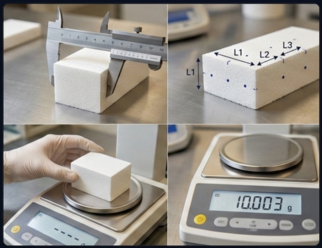
EPS block measuring points and analytical balance setup.
EN 1602 // QA/QC METRICS
Apparent Density Protocol
Any surface skins or facings not integral to the EPS for its intended application must be removed prior to measurement.
Specimens conditioned in a climate chamber at $23 \pm 2^\circ\text{C}$ and $50 \pm 5\% \text{ RH}$ for a minimum of 24 hours.
Conditioning continues until constant mass is achieved ($\Delta m < 0.1\%$ between two successive weighings 24 hours apart).
After conditioning, measure length, width, and thickness at several clearly defined points (per EN 822/823).
Take three measurements per dimension; use the average. Accuracy must be $\pm0.5\%$ or $\pm0.5 \text{ mm}$ (whichever is greater).
Calculate specimen volume ($V = l \times b \times t$).
Weigh the conditioned specimen to determine mass ($m$).
Calibrated analytical balance (accuracy $\pm0.1\%$ of specimen mass).
Vernier calipers or steel rule with fine graduations (resolution $0.1 \text{ mm}$).
Climate-controlled conditioning chamber.
The apparent density is computed as:
$$ \rho_a = \frac{m}{l \cdot b \cdot t} $$
Report includes average $\rho_a$, standard deviation, and Coefficient of Variation (COV) for the sample set.
PART 1: EXPANDED POLYSTYRENE (EPS)
Dimensional Stability (EN 1603 / 1604)
ENGINEERING CONTEXT
The system relies on high-tolerance "Lego-type" interlocks to prevent concrete slurry leakage. Severe hygrothermal distortion will induce artificial load eccentricities ($e_{acc}$) in the assembled wall, triggering premature $P-\Delta$ buckling.
SETUP SUMMARY
Dimensions: $200 \times 200 \times 75$ mm (Coupled with Density specs).
Protocols: Normal (EN 1603 at $23^\circ\text{C}, 50\%\text{RH}$) & Severe (EN 1604 at $70^\circ\text{C}, 90\%\text{RH}$ for 48h).
EXPECTED OUTPUTS
Strains must not exceed the stringent thresholds of $\text{DS(N)2}$ and $\text{DS(70,-)1}$ classifications.
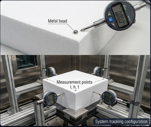
EPS specimen showing reference marks for l, h, t tracking before and after climate exposure.
EN 1603 / EN 1604 // HYGROTHERMAL DISTORTION
Dimensional Stability Protocol
Use same specimens from EN 1602 (Density Test) to maintain perfect statistical coupling.
Apply reference marks near the center of each edge (for length/width) and center of large faces (for thickness).
Initial conditioning at $23 \pm 2^\circ\text{C}$ and $50 \pm 5\% \text{ RH}$ until constant mass is achieved. Take initial measurements ($l_0, h_0, t_0$).
As defined in EN 13163 (typically change in mass < 0.1% over 24h).
After this initial conditioning and initial measurement, the specimens are then subjected to the test storage period.
After conditioning, the dimensions (length, width, and thickness) of each specimen must be carefully measured at several clearly defined points using calibrated instruments. EN 1602 references EN 822 for length and width measurement and EN 823 for thickness measurement. Typically, three measurements are taken for each dimension, and the average is used.
Measurements should be made to an accuracy of ±0.5% or ±0.5 mm, whichever is the greater precision.
The volume $(V)$ of each specimen must be calculated from its average measured dimensions ($V=l_b×h_b×t_b$).
Each conditioned specimen must be weighed using a calibrated balance to determine its mass $(m)$.
Condition 1 (Normal): Store at $23^\circ\text{C}, 50\% \text{ RH}$ for specified period.
Condition 2 (Severe): Expose to $70 \pm 2^\circ\text{C}$ and $90 \pm 5\% \text{ RH}$ for $48 \pm 1$ hours in environmental chamber.
Remove and re-condition at normal lab environment for 6 to 24 hours.
Re-measure dimensions ($l_1, h_1, t_1$) at the exact reference marks.
WARNING: Do not use severe-tested specimens for subsequent mechanical tests due to polymer matrix relaxation.
Instrumentation
Calibrated digital calipers (resolution $0.1 \text{ mm}$) for length and width.
Micrometer or thickness gauge for thickness measurement.
Environmental chamber capable of maintaining specified temperature and humidity conditions.
Relative dimensional changes calculated for all principal axes:
Assesses potential degradation of the EPS-concrete interface bond and long-term thermal bridging due to moisture ingress over the structure's service life.
SETUP SUMMARY
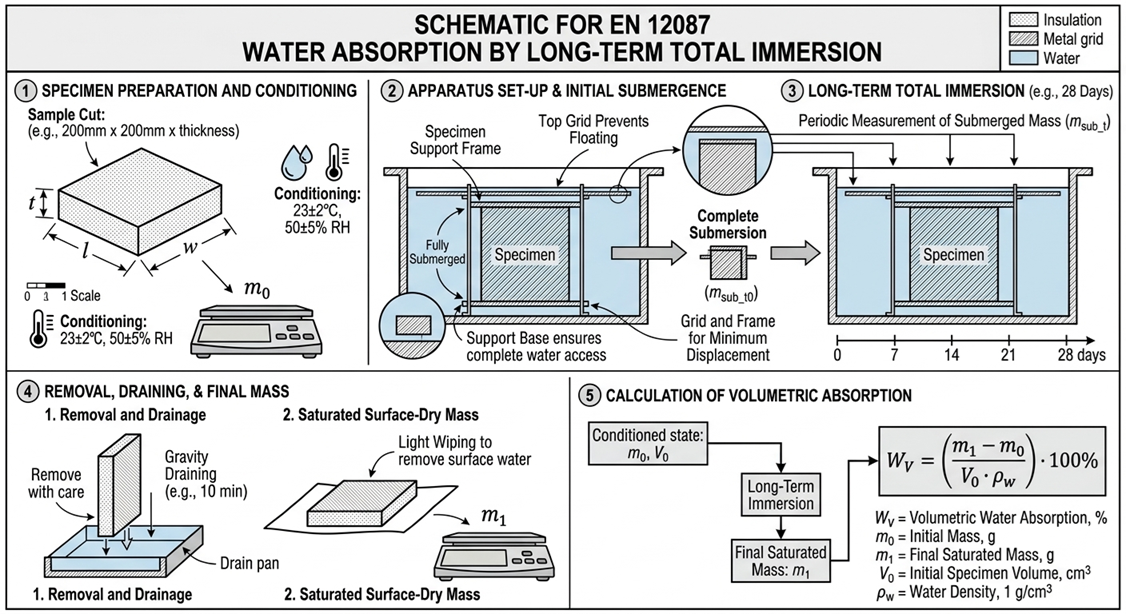
Dimensions: $200 \times 200 \times 45$ mm (Method 2A).
Protocol: Total horizontal immersion in tap water tank for 28 days.
EXPECTED OUTPUTS
Volumetric water absorption ($W_{lt}$). Critical for verifying structural and thermal durability boundaries.
Water tank setup showing fully submerged EPS specimens with spacers.
EN 12087 // DURABILITY METRICS
Water Immersion Protocol
Use same blocks from Apparent Density to utilize existing initial mass ($m_0$) and volume ($V_0$).
Specimens must be free of facings/skins.
Immerse horizontally in tap water at $23 \pm 2^\circ\text{C}$. Top surface must be $10 \pm 5 \text{ mm}$ below water level.
Use spacers to ensure free water circulation on all faces.
After 28 days, remove and drain on an edge screen for exactly 10 minutes.
Blot surface water with a damp cloth (without compressing EPS).
Immediately weigh to determine wet mass ($m_{28}$).
Volumetric water absorption ($W_{lt}$) calculated by mass difference relative to water density ($\rho_w \approx 1000 \text{ kg/m}^3$):
Evaluates formwork resistance against fresh concrete hydrostatic pressure ($\approx 2400 \text{ kg/m}^3$) and extracts the compressive elastic modulus ($E_{ec}$) and Poisson's ratio ($\nu_{eps}$) for 3D confinement modeling.
SETUP SUMMARY
Crushing (Yield): $100 \times 100 \times 50$ mm.
Buckling (Instability): $70 \times 70 \times 70$ mm.
Protocol: Disp. control at $0.1 d_0 \text{ /min}$.
EXPECTED OUTPUTS
Compressive stress at 10% strain ($\sigma_{10}$), plastic energy absorption, and $\nu_{eps}$.
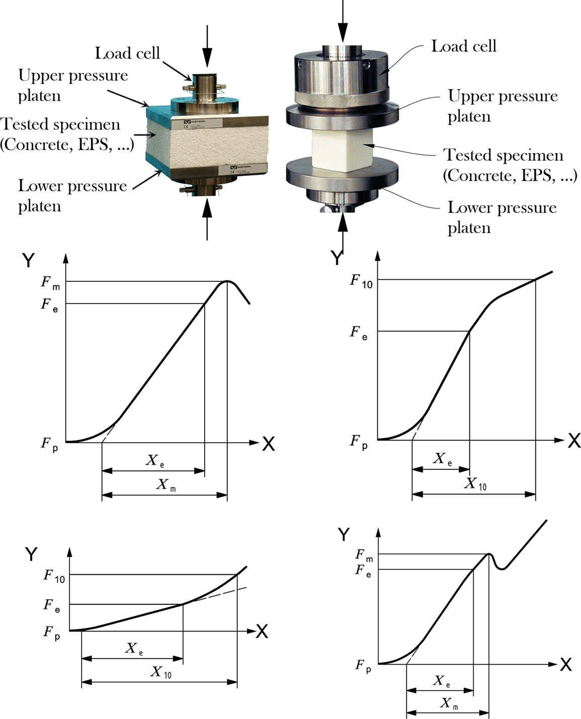
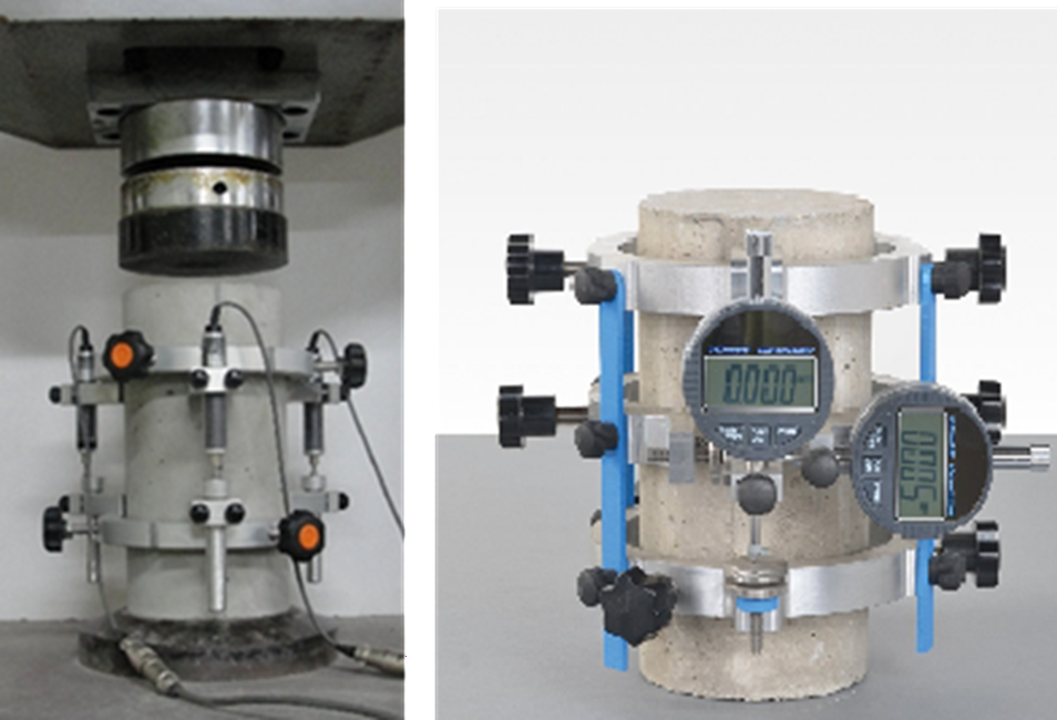
UTM setup with parallel platens, showing vertical and horizontal LVDTs tracking transverse expansion ($\Delta w$).
EN 826 + 3D EXTENSION // CONFINEMENT MECHANICS
Compression & Poisson Protocol
Specimen Preparation: Measure initial dimensions ($l_0, w_0, d_0$) to calculate the exact initial cross-sectional area ($A_0$). Apply a high-contrast stochastic speckle pattern to the observation faces for optical tracking. Center the specimen perfectly between the rigid, parallel platens of the low-capacity UTM.
DIC Setup & Calibration: Position the 3D DIC multi-camera array facing the speckled specimen.
SPECIAL NOTE ON DIC POSITIONING: The 3D DIC cameras must be explicitly focused and calibrated on the mid-height region of the specimen. This isolates the pure lateral Poisson expansion ($\Delta w$) and avoids the artificial lateral restraint (friction) induced by the steel loading platens at the top and bottom boundaries.
Alignment: Center the EPS specimen perfectly between the rigid, parallel platens of the low-capacity UTM to prevent parasitic load eccentricities.
Apply Standard Pre-load: Apply a strictly controlled pre-load of $250 \pm 10 \text{ Pa}$ ($0.25 \text{ kPa}$).
*Definition: Mandated by EN 826, this seating load establishes the exact zero-deformation reference point ($X_0$). It ensures full, flush contact between the platens and the EPS surface, eliminating initial gap-closure anomalies without inducing premature cellular yielding.
Loading Phase: Apply the compressive load under strict displacement control at a constant deformation rate of $0.1 \times d_0 \text{ mm/min}$ (e.g., $5 \text{ mm/min}$ for a $50 \text{ mm}$ thick block).
DIC Virtual Extensometers (8-Point Layout): Post-test, draw 8 virtual gauge points offset by $0.1h$ and $0.1b$ from the specimen edges.
Global Core Strain: Calculate displacement between vertical pairs (1-2) and (3-4). Compare them to instantly verify if the UTM platens rotated (eccentricity).
Localized Core Strain: Calculate displacement between mid-height pairs (5-6) and (7-8). This measures the pure constitutive material behavior ($E_{ec}$), bypassing the platen friction boundaries entirely.
Data Acquisition: Continuously synchronize the UTM force/axial displacement data with the full-field DIC strain matrix. Terminate the test once the relative axial deformation safely exceeds 10% ($\varepsilon_{10}$) or post-yield crushing stabilizes.
DAQ SYNCHRONIZATION (BNC/ANALOG INPUT): To eliminate temporal mismatch during post-processing, a BNC coaxial cable must connect the UTM's analog load output (0-10V) directly to the 3D DIC DAQ system. This ensures the optical virtual strains and the mechanical load are recorded at the exact same physical timestamp.
Low-capacity UTM (10-20 kN) to avoid load-cell resolution errors.
Full-Field 3D DIC System (replaces physical machine LVDTs to eliminate frame compliance and platen friction errors).
Analog/Digital Converter (A/D) for direct UTM-to-DIC synchronization.
$$ \nu_{eps} = -\frac{\varepsilon_t}{\varepsilon_a} = -\frac{(\Delta w / w_0)}{(\Delta h / h_0)} $$
*Strictly required to quantify passive lateral confinement pressure ($f_{cc}$) on concrete core.
PART 1: EXPANDED POLYSTYRENE (EPS)
Tensile Strength (EN 1607)
ENGINEERING CONTEXT
Quantifies the internal cohesive strength of the EPS ($\sigma_{mt}$), defining the absolute upper limit of the interface bond capacity between the EPS formwork and the concrete lattice before delamination.
SETUP SUMMARY
Dimensions: $100 \times 100 \times 50$ mm.
Protocol: Displacement control, failure between 1 and 10 minutes ($\approx 10 \text{ mm/min}$).
EXPECTED OUTPUTS
Ultimate tensile strength ($\sigma_{mt}$) and failure mode classification (cohesive EPS failure vs. adhesive failure).
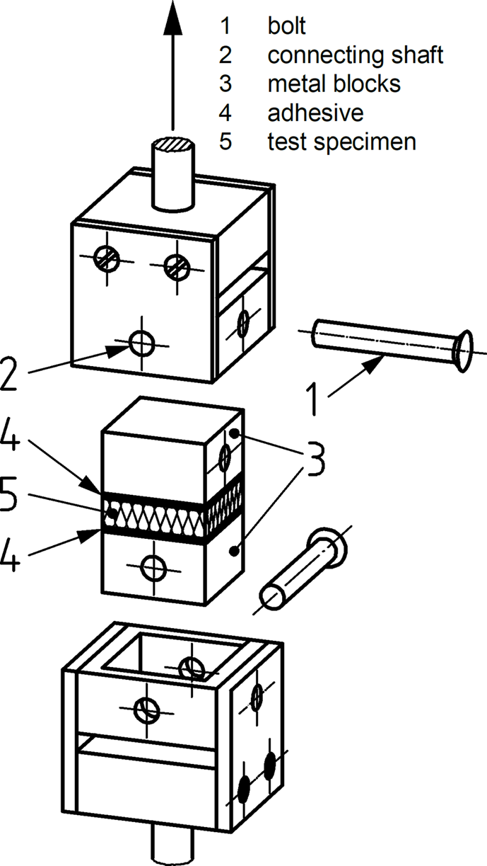
Tension specimen with adhered steel blocks and universal joint grips.
EN 1607 // COHESIVE LIMITS
Orthogonal Tension Protocol
Specimen Preparation: Precisely cut EPS blocks to $100 \times 100 \times 50 \text{ mm}$. Accurately measure the initial dimensions to establish the exact cross-sectional area ($A_0$). Ensure the two main loading faces are perfectly flat and parallel.
Adhesive Bonding & Curing: Apply a thin, even layer of high-strength structural epoxy to adhere rigid steel or aluminum loading plates to the two main faces of the EPS block. Condition the assembly in a climate chamber ($23 \pm 2^\circ\text{C}$ and $50 \pm 5\% \text{ RH}$) until the adhesive is fully cured and the EPS reaches moisture equilibrium.
*Requirement: The adhesive's tensile strength must significantly exceed the EPS cohesive strength ($\sigma_{mt} \approx 200 \text{ kPa}$). If the bond fails at the glue line (adhesive failure), the test is invalid and must be discarded.
UTM Mounting & Alignment: Mount the steel-EPS-steel sandwich assembly into the grips of the 10 kN Universal Testing Machine (UTM).
KINEMATIC ALIGNMENT MANDATE: The loading blocks must be connected to the UTM crossheads via universal kinematic joints (self-aligning grips). Cellular foams are extremely sensitive to eccentric tension. Even a $1^\circ$ misalignment will induce parasitic bending moments, causing a premature "zipper-effect" tearing at the specimen edges rather than true uniform axial rupture.
Loading Phase: Apply a pure axial tensile load under strict displacement control. Set the constant crosshead speed (e.g., $10 \text{ mm/min}$) such that complete macroscopic failure of the EPS occurs strictly within the EN 1607 specified time window of 1 to 10 minutes.
Synchronized DIC: Utilize the 3D DIC (hardware-synced to the UTM load cell) tracking an 8-point virtual gauge layout offset by $0.1h/0.1b$. Comparing the left vs. right virtual strain pairs physically proves the universal joints eliminated all bending moments.
Data Acquisition & Classification: Continuously record the tensile force ($F$) until separation. Record the maximum peak load ($P_{max}$). Crucially, upon failure, inspect the fracture plane and record the Failure Mode Classification (e.g., reporting the exact percentage of cohesive failure within the EPS cellular matrix versus any partial adhesive peeling at the plates).
Report percentage of cohesive failure within the EPS matrix.
PART 1: EXPANDED POLYSTYRENE (EPS)
Bending Strength / Flexure (EN 12089)
ENGINEERING CONTEXT
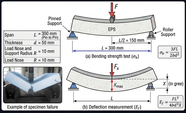
Defines the flexural modulus ($E_f$) and bending strength ($\sigma_b$) to evaluate the bulging of the continuous EPS faces under the hydrostatic pressure of SCC casting.
Load-deflection curves, $\sigma_b$, and verification of material homogeneity across the cross-section.
Three-point bending setup showing loading nose, supports, and mid-span deflection.
EN 12089 // FORMWORK BULGING
Flexure Protocol
Specimen Preparation & Sourcing: Extract and condition two distinct specimen groups at $23 \pm 2^\circ\text{C}$ and $50 \pm 5\% \text{ RH}$:
1. Standard Bulk (Part E): $300 \times 150 \times 50 \text{ mm}$ cut from the main insulation faces.
2. Scaled Ribs (Part R): $150 \times 70 \times 20 \text{ mm}$ extracted directly from the internal transverse ribs. Accurately measure the width ($b$) and depth ($d$) at the mid-span.
*Testing the ribs directly quantifies the structurally stiffer "as-molded skin" that actually resists the fresh concrete hydrostatic pressure.
Kinematic Setup & Span Calibration: Position two parallel cylindrical support rollers in the UTM. Strictly calibrate the testing span ($L_s$) to exactly $5 \times \text{thickness} (5d)$.
• For Standard ($d=50 \text{ mm}$): $L_s = 250 \text{ mm}$.
• For Ribs ($d=20 \text{ mm}$): $L_s = 100 \text{ mm}$.
THE "MOLDED SKIN" EFFECT ISOLATION: During the EPS bead expansion process, the surfaces contacting the mold form a denser, stiffer "skin." By testing the $70 \text{ mm}$ wide internal ribs with their intact as-molded skins, and comparing the flexural modulus ($E_f$) to the cut bulk EPS, we empirically quantify the actual anisotropic stiffness resisting the hydrostatic pressure of the fresh concrete slurry.
Specimen Alignment & Indentation Prevention: Center the specimen on the supports, ensuring the longitudinal axis is perfectly perpendicular to the loading nose.
*Requirement: The loading nose and supports must have a specified radius (e.g., $5$ to $20 \text{ mm}$) based on specimen thickness to prevent premature localized crushing (indentation) before pure flexural failure occurs at the extreme tension fiber.
Hardware-Synced DIC: Connect the UTM load cell to the DIC DAQ via analog BNC.
DIC 6-Point Virtual Extensometer Layout: Due to the lateral camera angle, absolute top/bottom faces are blind. Draw 6 virtual points offset by $0.1h$ from the boundaries:
True Deflection: $\Delta_{pure} = v_4 - (v_2 + v_6)/2$. This mathematically filters out the EPS crushing/indenting into the steel support rollers.
Core Squeezing: Calculate $v_3 - v_4$. Proves if the thickness remains constant (validating First-Order Shear Deformation Theory).
Neutral Axis Shift: Extract horizontal strain ($\varepsilon_{xx}$) gradient between points 3 and 4 to locate the exact neutral axis prior to flexural fracture.
Loading Phase: Apply the compressive mid-span load using strict displacement control. The constant crosshead speed (e.g., $10 \text{ mm/min}$ for the standard block) must be calibrated so that macroscopic flexural failure occurs strictly within the 1 to 10 minute window dictated by EN 12089.
Data Acquisition & Failure Observation: Continuously log the applied force ($F$) and the mid-span deflection ($\Delta$) via LVDT or crosshead encoder. Record the ultimate load ($P_{max}$) and verify the failure mode (valid tests must fracture in tension at the bottom face within the middle third of the span).
1. Ultimate Bending Strength ($\sigma_b$):
Assuming elastic Bernoulli-Euler kinematics at failure, where $M_{max} = \frac{P_{max} L_s}{4}$ and Section Modulus $S = \frac{b d^2}{6}$:
$E_f$: Flexural modulus of elasticity ($\text{N/mm}^2$)
$I$: Second moment of area ($I = \frac{b d^3}{12} \text{ mm}^4$)
Assumption: Shear deformation ($\delta_v = \frac{P L_s}{4 A G_{eps}}$) is considered negligible due to the $L_s/d = 5$ slenderness ratio constraint.
PART 1: EXPANDED POLYSTYRENE (EPS)
Direct Shear Strength (EN 12090)
ENGINEERING CONTEXT
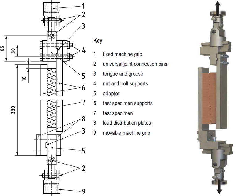
Directly quantifies the EPS shear modulus ($G_{eps}$) and ultimate shear strength ($\tau_u$), strictly required to define the shear compliance of the "Vierendeel" concrete frame within the EPS boundary.
SETUP SUMMARY
Dimensions: $250 \times 50 \times 50$ mm (Single-shear configuration).
Setup: Rigid plates adhered to parallel faces. Custom universal joint fixture ensures pure shear state through centroid.
Shear testing apparatus with rigid plates sliding parallel to each other.
EN 12090 // VIERENDEEL COMPLIANCE
Direct Shear Protocol
Specimen Preparation: Precisely cut EPS blocks to the standard single-shear dimensions of $250 \times 50 \times 50 \text{ mm}$. Accurately measure the length and width of the sheared faces to establish the exact shear area ($A_{shear} \approx 12,500 \text{ mm}^2$) and measure the specimen thickness ($t \approx 50 \text{ mm}$) to calculate shear strain ($\gamma$).
Adhesive Bonding & Curing: Apply a high-strength structural adhesive to adhere thick, rigid steel plates to the two opposite $250 \times 50 \text{ mm}$ faces of the EPS. Condition the assembly at $23 \pm 2^\circ\text{C}$ and $50 \pm 5\% \text{ RH}$ until fully cured.
*Requirement: The steel plates must be significantly stiffer than the EPS to ensure uniform shear stress distribution. The adhesive must possess a shear strength far exceeding the EPS ($\tau_u \approx 150 \text{ kPa}$) to force cohesive failure strictly within the foam matrix.
UTM Mounting & Alignment: Mount the steel-EPS-steel assembly into the specialized single-shear testing fixture within the UTM.
PURE SHEAR STATE & PARASITIC PEELING: Single-shear configurations are highly susceptible to eccentricities. The loading plates must be offset such that the applied line of action passes exactly through the geometric centroid of the EPS interface. If misaligned, a parasitic bending moment is induced, causing the EPS to peel (fail in tension) rather than shear, which completely invalidates the secant shear modulus ($G_{eps}$) required for your Vierendeel compliance NLFEA models. Universal kinematic joints are mandated to resolve any residual moments.
Instrumentation Setup: Attach high-precision LVDTs directly between the two rigid loading plates (not relying on crosshead movement). This strictly isolates the relative shear slip ($\delta_s$) of the EPS from any compliance or seating adjustments in the testing fixture.
Loading Phase: Apply the shear force parallel to the bonded faces using strict displacement control. Set a constant crosshead rate (e.g., $0.5 \text{ mm/min}$) to guarantee that macroscopic shear failure occurs smoothly within the EN 12090 specified window of 1 to 10 minutes.
Data Acquisition & Classification: Continuously record the applied force ($F$) against the relative shear slip ($\delta_s$). Extract the ultimate peak load ($P_{max}$) and classify the failure mode (validating that a minimum of 90% of the failure occurred as cohesive shear-off within the EPS cells).
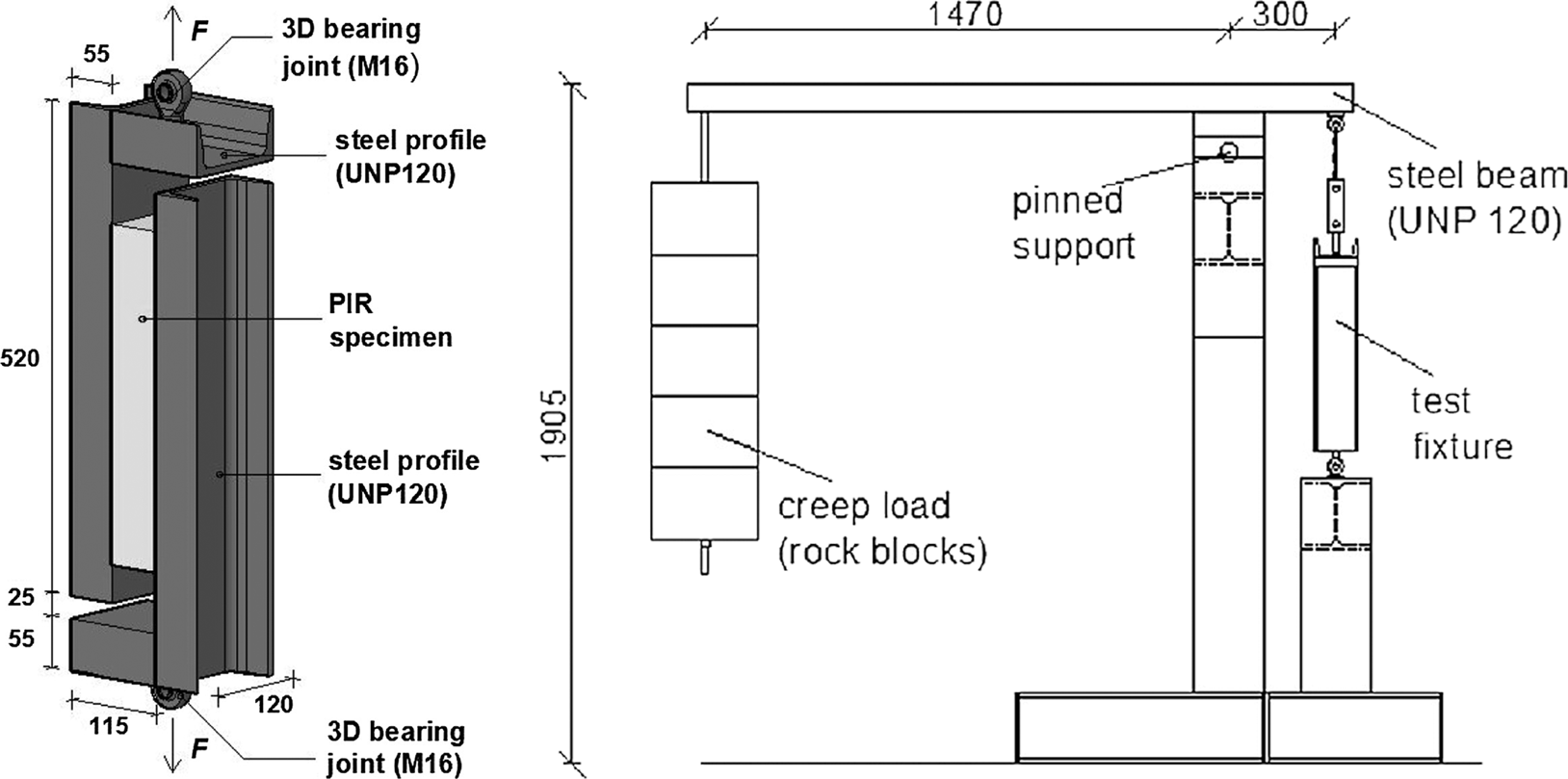
Polymeric foams exhibit significant viscoelasticity. Long-term shear compliance exacerbates $P-\Delta$ instability in slender EPSB-RC walls over their service life.
SETUP SUMMARY
Dimensions: $360 \times 120 \times 30$ mm.
Setup: Custom gravity-lever kinetic fixture in climate chambers ($20^\circ\text{C}$ & $30^\circ\text{C}$ at $55\%\text{RH}$).
Protocol: Sustained loads at 20%, 40%, 60% of $\tau_u$ for $\ge 1000$ hours.
EXPECTED OUTPUTS
Shear strain & creep compliance over time. Used to degrade Effective Shear Stiffness ($D_{Q_{eff}}$).
Shear creep testing apparatus, detailing the sustained gravity loading mechanism and environmental chamber enclosure.
VISCOELASTICITY // LONG-TERM STABILITY
Shear Creep Protocol
Specimen Preparation & Bonding: Precisely cut EPS blocks to $360 \times 120 \times 30 \text{ mm}$. Thoroughly clean the mating steel support profiles with acetone to remove any machining oils. Bond the EPS faces to the steel profiles using a rigid 2-component polyurethane (PU) structural adhesive.
Curing & Matrix Penetration: Apply a slight, uniform compressive pressure (utilizing the self-weight of the top steel profile) during the curing phase.
*Requirement: This pressure forces the PU adhesive to penetrate the open cellular matrix of the cut EPS surface, establishing a deep mechanical interlock rather than a superficial surface bond. Allow to cure for 1 to 7 days.
Fixture Mounting & Thermal Equilibrium: Install the bonded assembly into the custom gravity-lever kinetic fixture located inside the environmental chamber. Crucially, allow the specimen to rest unloaded at the target testing temperature ($20^\circ\text{C}$ or $30^\circ\text{C}$ at $55\% \text{ RH}$) for at least 24 hours prior to loading to prevent initial thermal expansion from corrupting the elastic slip readings.
VISCOELASTIC STEADY-STATE & THERMAL COUPLING: Polymeric foams undergo immediate elastic deformation ($\gamma_e$) followed by transient primary creep, eventually stabilizing into a constant-rate "secondary" creep. Because EPS shear compliance dictates the long-term Vierendeel flexibility of the wall, failing to reach the secondary creep phase ($\ge 1000$ hours) will drastically underestimate the 50-year $P-\Delta$ amplification. Furthermore, strict environmental control ($\pm 1^\circ\text{C}$) is mandated; minor temperature fluctuations will induce volumetric thermal strains that falsely register as mechanical shear slip on the LVDTs.
Sustained Loading Phase: Carefully and smoothly release the sustained dead loads (rock/concrete blocks) onto the lever beam to achieve the target shear stress levels: 20%, 40%, and 60% of the previously established ultimate shear strength ($\tau_u \approx 150 \text{ kPa}$). Avoid any dynamic shock or impact during load application.
Data Acquisition & Extrapolation: Continuously monitor the relative shear displacement ($\delta_s$) using high-precision LVDTs ($\pm 25\text{ mm}$ stroke) mounted on opposite faces to average out any minor out-of-plane twisting.
Record data logarithmically (high frequency initially, decreasing over the $\ge 1000$ hour duration) until the creep rate stabilizes, enabling the rigorous calibration of Findley's Power Law parameters ($m, n$).
High-precision LVDTs ($\pm 25\text{ mm}$ range) and redundant mechanical dial gauges on opposite faces.
Load Levels: Base $\tau_u \approx 6.48 \text{ kN}$:
$P_{20\%} \approx 1.30 \text{ kN}$
$P_{40\%} \approx 2.59 \text{ kN}$
$P_{60\%} \approx 3.89 \text{ kN}$
Findley’s Power Law Calibration:
Predicts time-dependent viscoelastic shear strain accumulation under sustained constant stress:
$$ \gamma(t) = \gamma_e + m \left(\frac{t}{t_0}\right)^n $$
$\gamma(t)$: Total shear strain at time $t$
$\gamma_e$: Instantaneous elastic shear strain at $t=0$
$m$: Stress-dependent creep coefficient (amplitude of transient creep)
$n$: Stress-independent material constant (viscoelastic flow rate)
$t_0$: Unit reference time (typically 1 hour)
PART 2: CONCRETE CORE (C30/37 SCC)
Fresh Properties & Shrinkage
ENGINEERING CONTEXT
The discrete "screen-grid" topology necessitates highly flowable SCC. Restraining shrinkage within the EPS grid induces pre-test micro-cracking, affecting initial secant stiffness.
SETUP SUMMARY
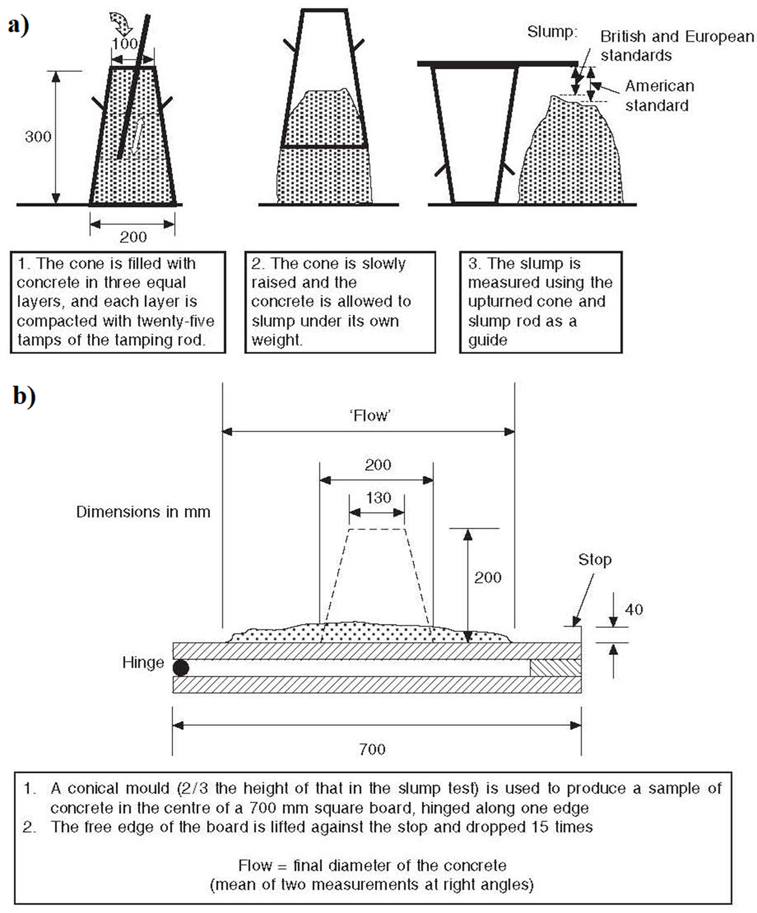
Rheology (EN 12350): Slump, Flow Table, SCC Slump-Flow. $d_{max} \le 12.5$ mm constraint.
Shrinkage (EN 12390-16): $100 \times 100 \times 400$ mm prisms.
EXPECTED OUTPUTS
$T_{500}$ viscosity, Visual Stability Index (VSI), and time-dependent shrinkage strain $\varepsilon_{cs}(t)$.
Slump-flow diameter measurement alongside a shrinkage prism with Demec points.
RHEOLOGY & TIME-DEPENDENCE
SCC & Shrinkage Protocols
SCC Slump-Flow: Place Abram's cone on base plate. Fill without tamping. Lift vertically. Measure final spread diameter and $T_{500}$ (time to reach 500mm spread). Assess VSI (Visual Stability Index) to ensure zero segregation.
Shrinkage: Demold $100 \times 100 \times 400$ mm prisms at 24 hours. Immediately instrument with Vibrating Wire Strain Gauges (VWSG) or Demec points.
Record length changes ($\Delta L$) at 1, 3, 7, 14, 28, 56, 90 days in climate room matching full-scale curing ($20^\circ\text{C}, 50\% \text{ RH}$).
The strict limitation of the maximum aggregate size to $d_{max} \le 12.5 \text{ mm}$ is mandated by three critical system constraints:
1. "Aggregate Arching" at Grid Intersections (Nodes): Unlike continuous walls, the EPSB-RC "screen-grid" requires fluid SCC to flow vertically down columns and branch laterally at sharp $90^\circ$ angles into horizontal ribs. Standard $20 \text{ mm}$ aggregates will collide and "arch" (jam) at these tight corners, causing severe segregation and leaving massive air voids (honeycombing) at the exact nodal intersections that govern Vierendeel shear capacity.
2. Reinforcement Congestion (Eurocode 2 / EFNARC): SCC passing ability dictates $d_{max} \le \text{clear spacing} - 5 \text{ mm}$ and $d_{max} \le c_{min} \times 0.8$. With $100 \text{ mm}$ narrow ribs containing longitudinal steel ($\phi 12$), cross-ties, and minimum internal cover ($15\text{-}20 \text{ mm}$), the physical passage gap is extremely restricted. The $12.5 \text{ mm}$ limit ensures cement paste and aggregate pass uniformly through the cage without blocking.
3. EU Commercial Sieve Fractions (EN 12620): For practical scaling and full-scale prototype construction (Phase 5), the mix design must align with Portuguese ready-mix plant capabilities. European standard aggregate fractions are sorted as $0/4 \text{ mm}$ (sand), $4/8 \text{ mm}$ (gravel), and $8/12.5 \text{ mm}$ (coarse). Specifying $\le 12.5 \text{ mm}$ perfectly aligns with commercial SCC availability.
Expressed in microstrain ($\mu\text{m/m}$). Calibrates pre-stress states in NLFEA prior to external loading.
PART 2: CONCRETE CORE (C30/37 SCC)
Compressive Strength & Density
ENGINEERING CONTEXT
Density ($\rho_c$) dictates dead-load $P-\Delta$ amplification. Compressive testing populates the pre-peak hardening branch (Thorenfeldt curve) and $f_{cm}$ for TSBCM in DIANA.
SETUP SUMMARY
Density (EN 12390-7): Archimedes' water displacement. Target: $2400 \text{ kg/m}^3$.
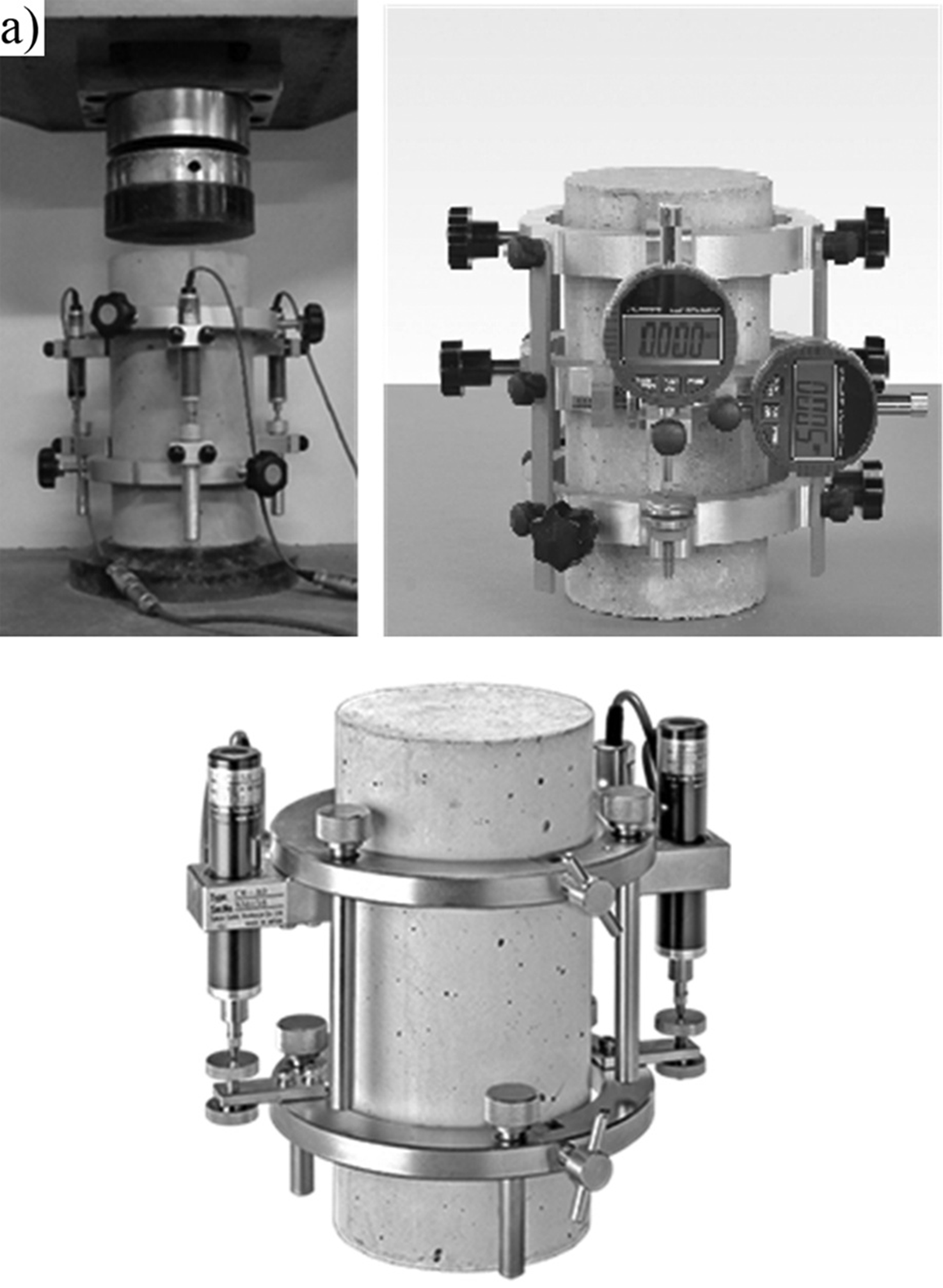
Compression (EN 12390-3): $\phi150 \times 300$ mm cylinders. $2000 \text{ kN}$ UTM.
Cylinder compression test with longitudinal compressometers.
EN 12390-3 / EN 12390-7 // MATRIX STRENGTH
Compression Protocol
Density: Weigh saturated surface-dry (SSD) specimen in air, then submerged in water to extract exact volume via Archimedes principle. Dry at $105^\circ\text{C}$ to get dry density.
Compression: Grind cylinder ends strictly parallel. Mount centrally in $2000\text{ kN}$ UTM.
Defines the exact stress threshold for the onset of the tensile softening branch (crack initiation) within the FEA Total Strain Based Crack Model.
SETUP SUMMARY
Dimensions: $\phi150 \times 300$ mm cylinders.
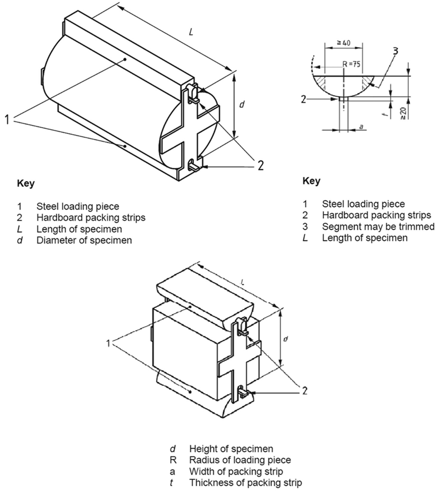
Setup: $2000 \text{ kN}$ UTM, diametral line loading with $4 \times 15$ mm hardboard packing strips.
EXPECTED OUTPUTS
Tensile splitting strength ($f_{ct,sp}$) to derive the direct tensile strength parameter ($f_{ctm}$).
Concrete mechanical testing configurations: Splitting tension test - Cylinder loaded diametrically with packing strips.
EN 12390-6 // CRACK INITIATION
Tensile Splitting Protocol
Lay cylinder on its side. Place one packing strip between lower platen and specimen, and another between upper platen and specimen, aligned along generatrices.
Center in $2000\text{ kN}$ compression machine.
Apply load continuously without shock at constant stress rate: $0.05 \text{ MPa/s}$.
Captures the initial secant modulus ($E_{c,s}$) strictly required for calculating global flexural rigidities ($EI$) and predicting elastic serviceability limit state (SLS) deflections.
SETUP SUMMARY
Dimensions: $\phi150 \times 300$ mm cylinders.
Setup: 3 continuous cycles between $\sigma_b = 0.5 \text{ MPa}$ and $\sigma_a = f_{cm}/3$.
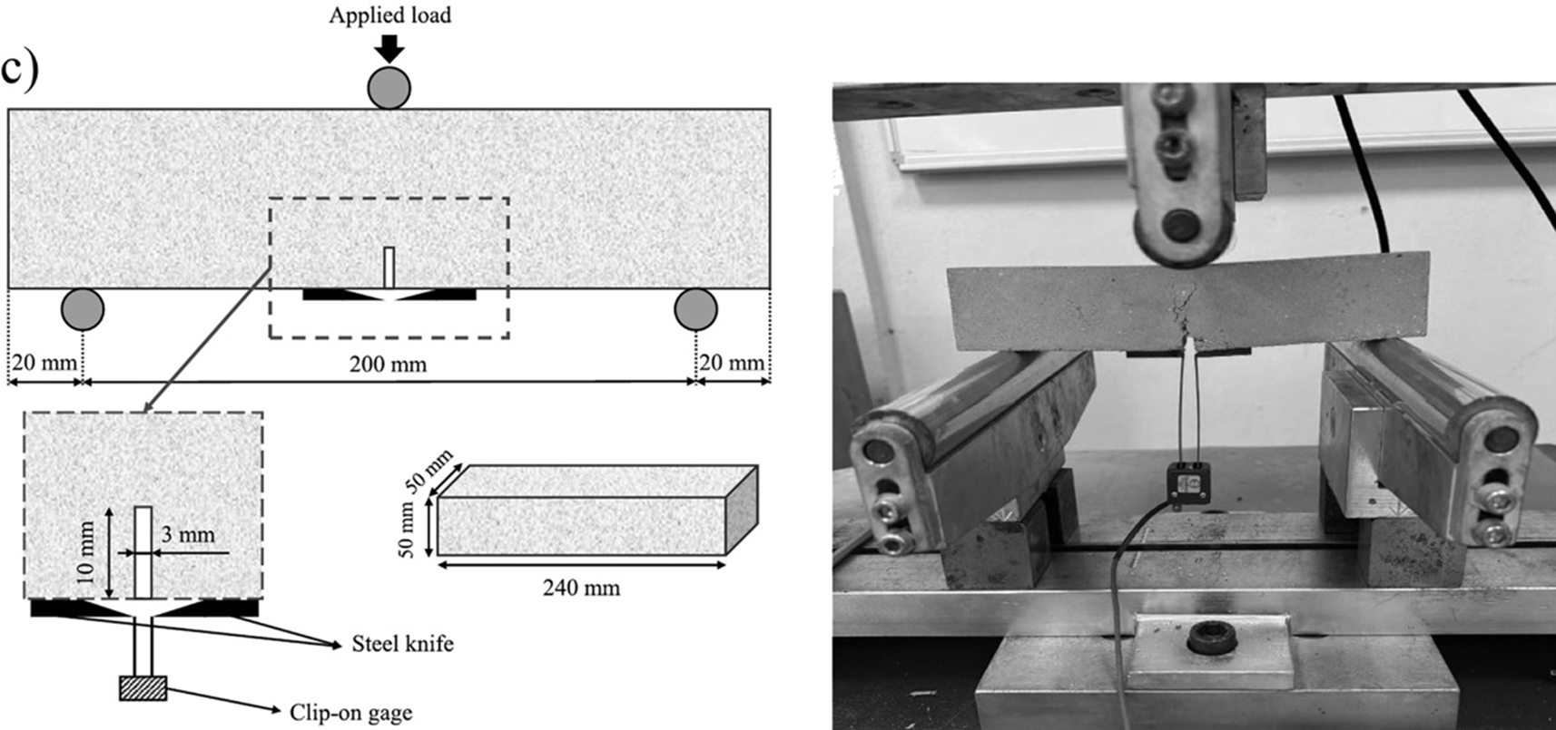
Quantifies specific energy required to propagate a tensile crack ($G_F$). Acts as the crack band regularizer ($h_{eq}$) in NLFEA to prevent spurious numerical mesh localization.
SETUP SUMMARY
Dimensions: $150 \times 150 \times 550$ mm notched prisms ($a=50$ mm notch).
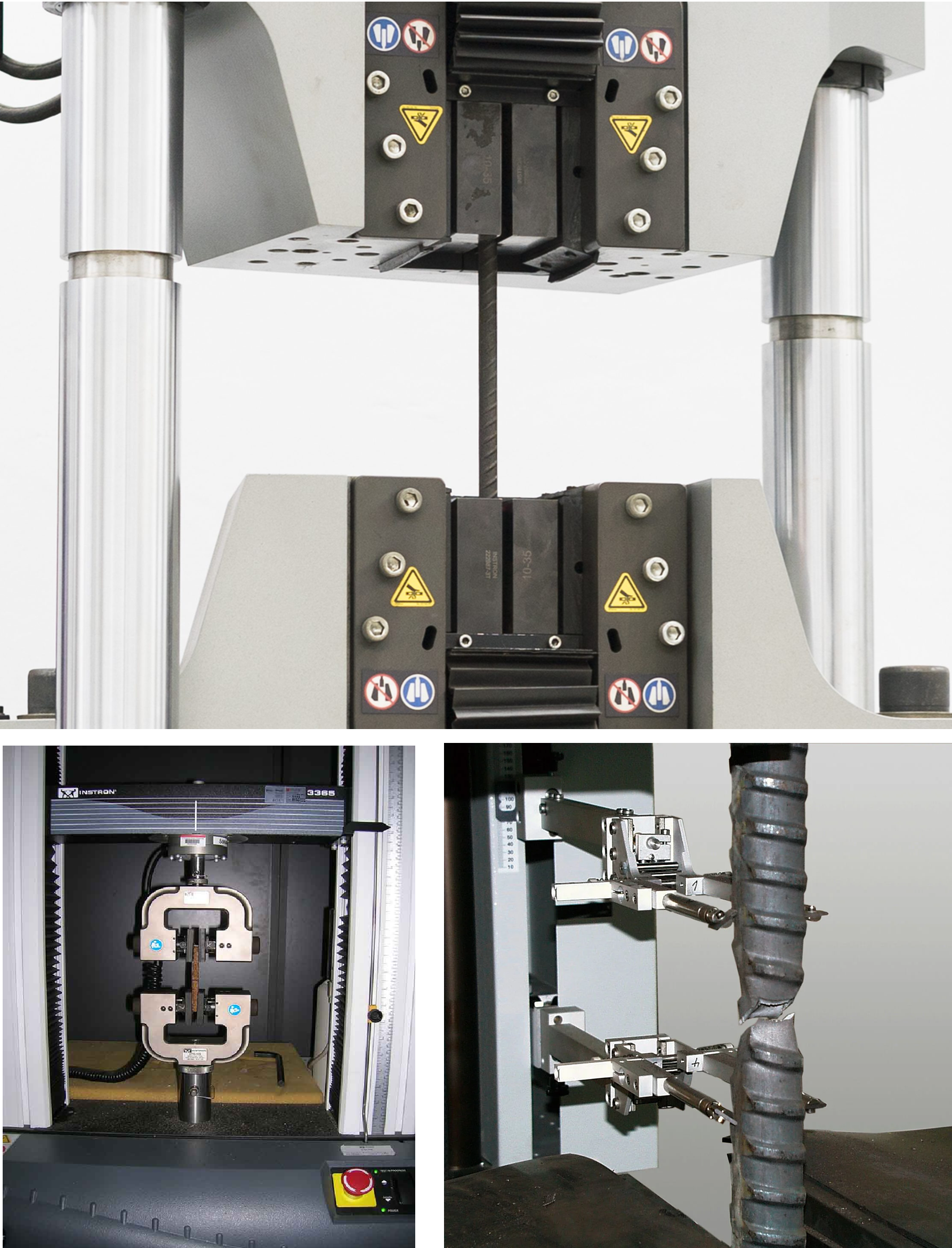
Establishes the highly ductile, elastoplastic baseline (yield plateau and strain hardening) which defines the ductile limit states in traditional reinforced concrete walls.
SETUP SUMMARY
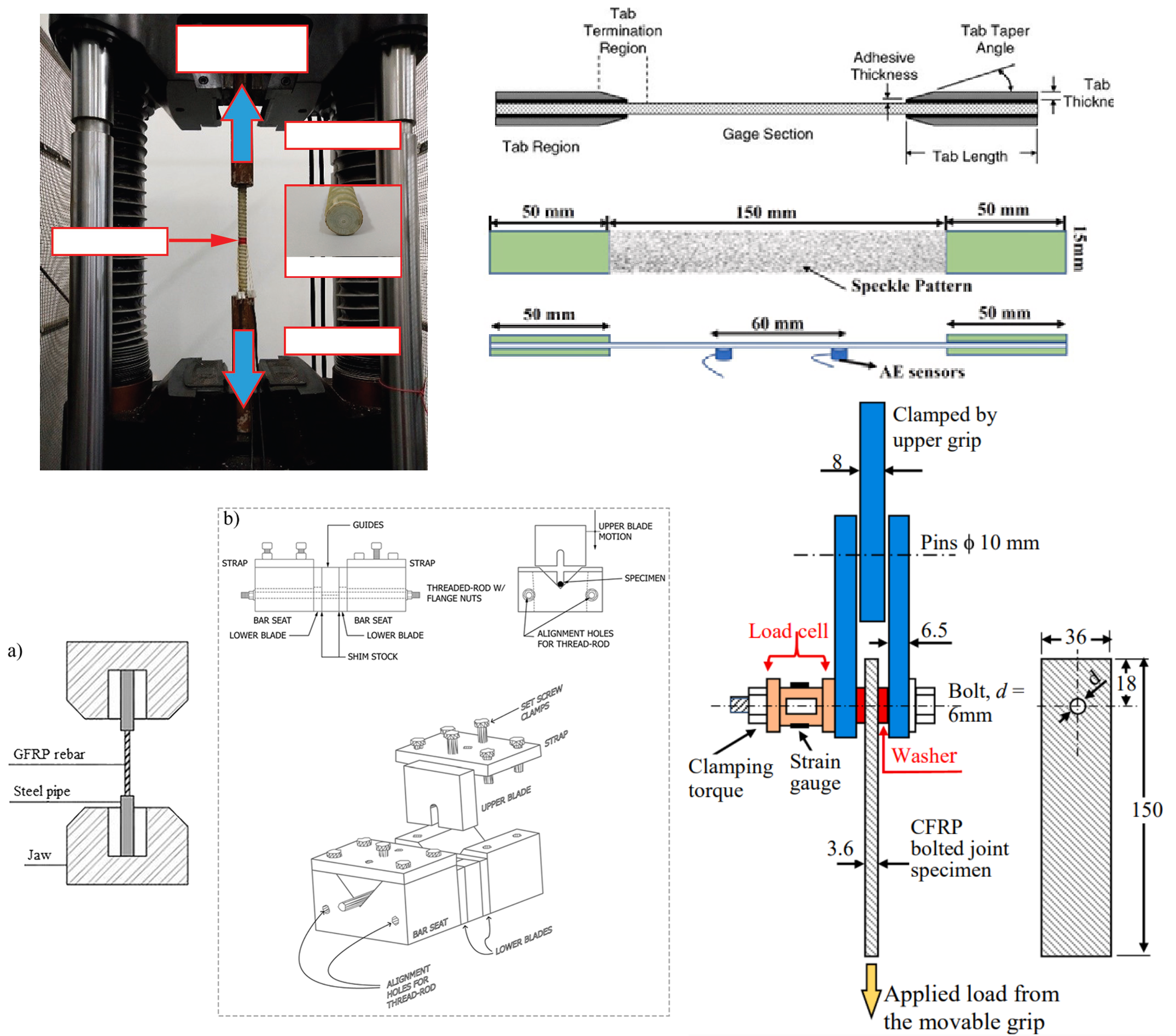
Dimensions: $\phi12 \times 500$ mm bars (Grade B500B).
Setup: 250 kN UTM, Class 1 clip-on extensometer. Strain control.
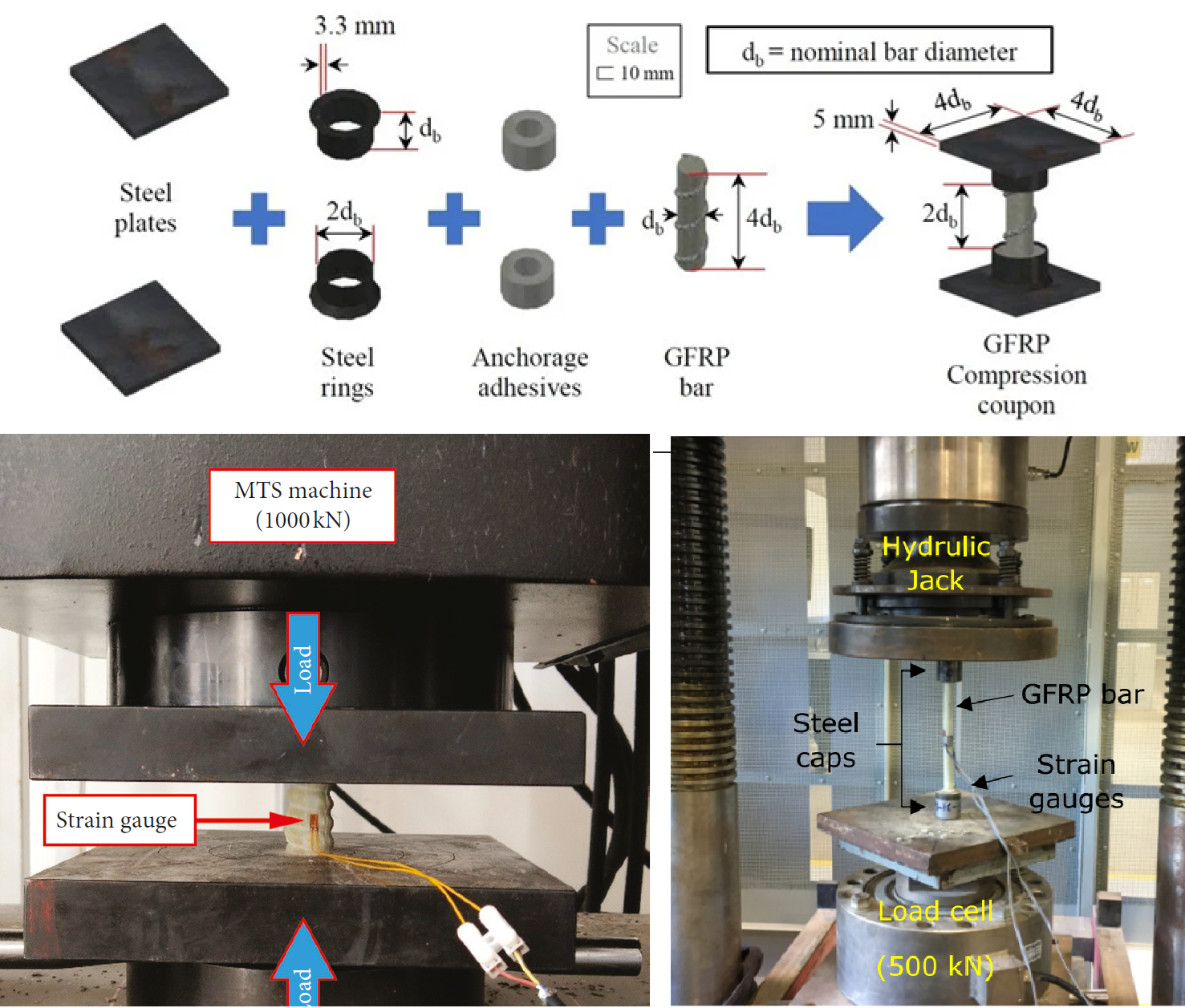
GFRP is highly anisotropic and weak in compression. Under cyclic rocking (Phase 5), flanged boundary elements face massive flexural compression causing fiber micro-buckling.
SETUP SUMMARY
Dimensions: Short segments. Unbraced length constrained to $L_e \le 2d_b$ ($24$ mm) to explicitly prevent Euler buckling.
Setup: Ground parallel ends between hardened steel platens.
Short GFRP coupon between parallel compression platens with DIC speckle.
ASTM D695 / D3410 // ANISOTROPY
GFRP Compression Protocol
Machine ends perfectly flat, parallel, and perpendicular to axis.
Place centrally between hardened steel platens. Ensure perfect alignment to prevent eccentric stress concentrations.
Apply load under displacement control ($1.0 \text{ mm/min}$).
Track strain via micro-extensometer or 3D DIC focused on central region.
Target Load Calculation:
Due to anisotropic fiber micro-buckling and matrix crushing, GFRP compressive strength ($f_{fc,u}$) is a fraction ($\eta_c$) of its tensile capacity. Assuming $\eta_c \approx 0.40$ for typical E-Glass/Vinyl-ester:
Assumption: Global Euler buckling is suppressed by strict geometric constraint ($\lambda \ll \lambda_{crit}$).
PART 3: REINFORCEMENT (STEEL & GFRP)
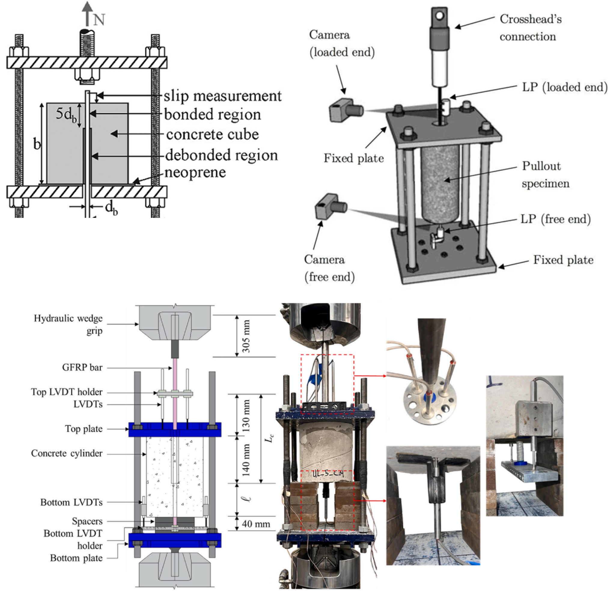
Bond-Slip Mechanics (ASTM D7913)
ENGINEERING CONTEXT
Quantifies stress transfer between rebar and concrete. GFRP sand-coating radically alters tension stiffening (residual concrete capacity between cracks) compared to ribbed steel.
SETUP SUMMARY
Dimensions: $200$ mm concrete cubes. Single central rebar.
Constraint: Embedment length restricted to $l_b = 5d_b$ ($60$ mm) to force interfacial slip, avoiding bar rupture.
EXPECTED OUTPUTS
Bond stress-slip curve ($\tau - s$) and ultimate bond strength ($\tau_{bu}$).
Direct pull-out fixture with LVDTs at loaded and free ends.
ASTM D7913 // TENSION STIFFENING
Bond-Slip Protocol
Debond excess bar length using PVC tubing/neoprene to leave exactly $l_b = 60 \text{ mm}$ active.
Mount in direct pull-out fixture. Reaction plate bears on concrete.
Attach high-precision LVDTs to loaded and free ends of bar.
Apply tension under strict slip control ($0.01 \text{ mm/s}$).
Assuming uniform shear stress distribution over the restricted embedment length ($l_b \le 5d_b$) and an ultimate sand-coated bond strength $\tau_{bu} \approx 15 \text{ MPa}$:
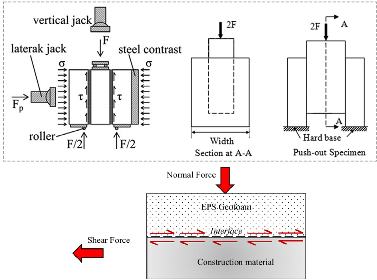
Validates the "Interface Integrity Constraint" ($\tau_{int,eff} \le \tau_{Rd}$). Interfacial shear is mathematically amplified by the inverse of the concrete area fraction ($\phi_x$) at the rib intersections.
SETUP SUMMARY
Dimensions: Central RC prism ($100 \times 100 \times 300$ mm) cast *in-situ* between two EPS blocks. $A_{contact} = 30,000 \text{ mm}^2$/face.
Setup: 50 kN UTM, rigid base with central void, 4x LVDTs.
EXPECTED OUTPUTS
Interface shear stiffness ($K_{interface}$) and ultimate shear transfer capacity.
Triplet push-out assembly on a rigid base with a central void.
INTERFACE MECHANICS // STABILITY CONSTRAINT
Triplet Push-Out Protocol
Specimen Fabrication (In-Situ Casting): rigidly brace two high-density EPS blocks ($100 \times 300 \text{ mm}$ interface area) at an exact spacing of $100 \text{ mm}$. Cast the C30/37 SCC directly into this cavity to form the central concrete prism ($100 \times 100 \times 300 \text{ mm}$).
*Requirement: Do NOT cast the concrete separately and glue it to the EPS. The specimen must be cast in-situ to replicate the exact hydrostatic pressure and the critical bleeding of cement paste into the macroscopic voids between the EPS beads.
Curing & Handling: Cure the triplet assembly in a controlled environment for 28 days. Extreme care must be taken during transport to the testing frame; any premature bending or torsion will pre-fracture the fragile chemical adhesion at the EPS-concrete boundary, ruining the initial stiffness ($K_{interface}$) data.
Fixture Setup & Alignment: Mount the cured triplet specimen onto a rigid, machined steel base plate featuring a central rectangular void.
THE INTERFACE INTEGRITY CONSTRAINT: The two outer EPS blocks must be fully supported by the solid perimeter of the steel base, while the central concrete core is positioned exactly over the void. The applied compressive load bears only on the concrete core. This forces 100% of the applied load to transfer through the two vertical EPS-concrete interfaces via pure shear stress ($\tau_{int}$), empirically validating whether the EPS ribs will prematurely decouple from the concrete lattice under extreme service loads.
Instrumentation Deployment: Affix a network of four (4) high-precision LVDTs (stroke: $\pm 5 \text{ mm}$, resolution: $0.001 \text{ mm}$). Anchor the LVDT bodies to the central concrete core and rest the probe tips on brackets glued to the adjacent EPS blocks. This explicitly isolates the relative longitudinal slip ($\delta_s$) across the shear planes.
Loading Phase: Apply vertical compression to the top of the central concrete core using a 50 kN UTM. Strict displacement control (e.g., $0.5 \text{ mm/min}$) is mandated to safely capture the sudden, quasi-brittle debonding and track the post-peak frictional sliding behavior.
Data Extraction & Verification: Continuously plot the Shear Force ($P/2$) vs. Relative Slip ($\delta_s$). Extract the ultimate shear capacity ($\tau_{Rd}$) and classify the failure: interface sliding vs. cohesive EPS tearing (where chunks of EPS remain permanently anchored to the concrete surface).
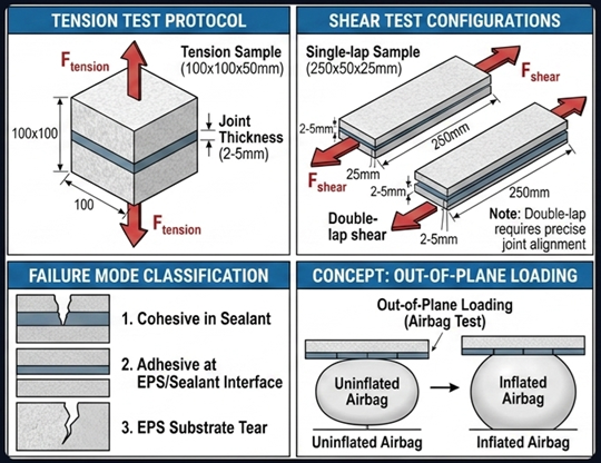
Evaluates if polyurethane-sealed EPS blocks act as a continuous structural skin or a hinged joint under out-of-plane loading (Airbag test).
SETUP SUMMARY
Tension: $100 \times 100 \times 50$ mm cube pulled orthogonally.
Shear: $250 \times 50 \times 25$ mm sheared longitudinally.
Setup: Maintain exact site joint thickness (2-5mm).
EXPECTED OUTPUTS
Interfacial normal/shear stiffness ($k_n, k_s$) and cohesive/adhesive failure mode classification.
EPS blocks joined by sealant undergoing direct tension and shear.
EN 1607/12090 ADAPTED // FORMWORK CONTINUITY
Sealant Joint Protocol
Specimen Fabrication & Joint Control: Cut standard EPS blocks into halves. Apply the specified low-expansion Polyurethane (PU) construction sealant to the mating surfaces.
*Requirement: The sealant joint thickness must be strictly controlled using precision spacers to exactly 2 to 5 mm, perfectly replicating the realistic on-site tolerances of the "Lego-type" mechanical interlocks.
Curing & Conditioning: Because PU sealants cure via ambient atmospheric moisture, the joined assemblies must be conditioned in a climate chamber at $23 \pm 2^\circ\text{C}$ and $50 \pm 5\% \text{ RH}$ for an extended period (typically 7 to 14 days) until the elastomeric core is completely cross-linked and stable.
Setup A: Orthogonal Tension (Adapted EN 1607): Adhere rigid steel plates to the outer EPS faces of a $100 \times 100 \times 50 \text{ mm}$ joined cube. Mount the assembly in a 10 kN UTM using universal kinematic joints to ensure pure axial tension perpendicular to the sealant plane, eliminating parasitic peeling moments.
Setup B: Direct Shear (Adapted EN 12090): Mount a $250 \times 50 \times 25 \text{ mm}$ joined assembly into a double-plate shear fixture. Align the force vector perfectly parallel to the longitudinal sealant line.
CONTINUOUS SKIN HYPOTHESIS & FAILURE MODES: The structural performance of the EPSB-RC system assumes the EPS acts as a continuous, passive confining skin. If the joint fails Adhesively (cleanly peeling off the EPS), the blocks decouple under dynamic racking, losing confinement. If the failure is Cohesively within the EPS matrix (foam tearing while the PU joint remains intact), it mathematically proves the sealant is stronger than the base material ($> 0.20 \text{ MPa}$). This explicitly justifies treating the assembled EPS formwork as a single, homogenous confining medium in the DIANA NLFEA models.
Loading Phase: Apply the loads under strict displacement control. For tension, utilize a crosshead speed of $10 \text{ mm/min}$. For shear, utilize a slower rate of $0.5 \text{ mm/min}$ to accurately capture the elastomeric shear distortion ($k_s$) of the PU joint before ultimate rupture.
Data Extraction & Verification: Continuously log Force vs. Displacement. Extract the ultimate joint capacities ($P_{max,t}$ and $P_{max,v}$), derive the interfacial normal and shear stiffnesses ($k_n, k_s$) for the 3D interface finite elements, and definitively classify the fracture surface (Cohesive vs. Adhesive).
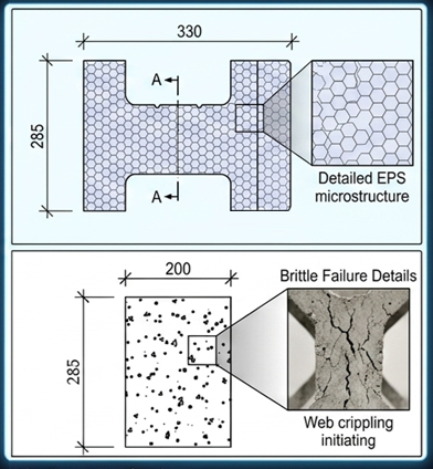
Explicitly isolates the structural components of the Representative Volume Element (RVE) to define the unconfined baseline before composite action is considered.
SETUP SUMMARY
Bare EPS: Hollow network only ($330 \times 250 \times 285$ mm).
Bare Concrete Lattice: Extracted from EPS post-curing ($200 \times 250 \times 285$ mm).
Setup: 2000 kN frame, vertical LVDTs.
EXPECTED OUTPUTS
Demonstrating severe vulnerability of the unconfined concrete lattice to premature, brittle nodal web crippling.
Unconfined bare concrete lattice in compression frame.
RVE DECONSTRUCTION // BASELINE VULNERABILITY
Bare RVE Protocol
Specimen Fabrication & EPS Extraction: 1. Bare EPS: Prepare the empty $330 \times 250 \times 285 \text{ mm}$ hollow EPS block.
2. Bare Concrete Lattice: Cast C30/37 SCC into the EPS formwork. Cure in a controlled environment for 28 days.
*Requirement: To isolate the bare lattice, the EPS must be removed entirely without inducing mechanical micro-cracks in the fragile concrete webs. Chemical dissolution (e.g., utilizing acetone) or precision hot-wire cutting is strictly mandated over mechanical stripping/prying.
End Preparation & Planeness: The top and bottom bearing surfaces of the extracted concrete lattice ($200 \times 250 \times 285 \text{ mm}$) must be ground perfectly flat and parallel. Any geometric unevenness will concentrate the entire 2000 kN load onto a single vertical rib, causing instantaneous localized failure rather than global lattice compression.
UTM Mounting & Alignment: Center the specimens perfectly between the rigid platens of the testing frames (50 kN UTM for the Bare EPS; high-stiffness 2000 kN UTM for the Bare RC Lattice).
UNCONFINED VULNERABILITY & WEB CRIPPLING: This test establishes the absolute minimum structural baseline. Because the concrete area fraction ($\phi$) is only 0.40, the isolated vertical ribs act as highly slender, unbraced columns. Under heavy axial load, the discrete nodal intersections will experience severe unconfined triaxial stress concentrations, leading to explosive, brittle web crippling. Capturing this exact failure mode is essential to definitively prove that the EPS formwork provides passive lateral restraint in the composite state.
Instrumentation Deployment: Affix four (4) vertical LVDTs between the machine platens (one at each corner) to measure global axial shortening and mathematically filter out any accidental load eccentricity. Mount two (2) horizontal LVDTs directly onto the outermost vertical concrete ribs to capture the lateral buckling dilation just prior to rupture.
Loading Phase: Apply the uniaxial compressive load under strict displacement control (e.g., $0.5 \text{ mm/min}$).
Note: Load-control is strictly prohibited for the bare lattice; the lack of confinement means post-peak failure will be violently explosive, requiring displacement control to safely trace the steep strain-softening branch.
Data Extraction & Verification: Continuously log Force vs. Axial/Lateral Displacement. Extract the ultimate unconfined capacities ($P_{max,bare}$) and document the precise location of the initial concrete spalling and nodal failure to calibrate the TSBCM damage parameters in DIANA.
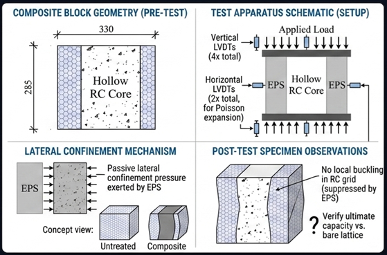
Tests the integrated EPSB-RC system to empirically validate the "Stiff-Core" hypothesis and quantify the passive lateral confinement pressure exerted by the EPS.
Enhanced ductility and ultimate capacity vs. the bare lattice, proving the EPS suppresses local grid buckling.
Fully encased composite EPSB-RC block in compression frame with horizontal LVDTs.
MANDER CONFINEMENT // STIFF-CORE HYPOTHESIS
Composite RVE Protocol
Specimen Fabrication (In-Situ Curing): Cast C30/37 SCC into the $330 \times 250 \times 285 \text{ mm}$ EPS formwork. Cure for 28 days in a climate-controlled environment.
*Requirement: Unlike the bare lattice protocol, the EPS formwork remains entirely intact. This preserves the undisturbed chemical adhesion and mechanical interlock at the EPS-concrete boundary, which is essential for activating composite action.
End Preparation & Planeness: Grind the top and bottom bearing surfaces perfectly flat and parallel. This guarantees uniform vertical strain distribution across both the discrete concrete webs and the surrounding EPS matrix, preventing localized punching shear or eccentric bearing at the loading boundaries.
UTM Mounting & Alignment: Center the fully composite RVE block between the rigid platens of the 2000 kN high-stiffness structural compression frame.
PASSIVE TRIAXIAL CONFINEMENT (MANDER MODEL): Under extreme axial compression, the internal concrete lattice attempts to dilate laterally (Poisson effect). The intact EPS formwork resists this dilation. Despite its low elastic modulus, the continuous geometric enclosure of the EPS generates a passive lateral confining pressure ($f_l$) on the concrete nodes. This shifts the concrete from a fragile uniaxial stress state into a robust triaxial stress state, effectively suppressing the explosive web crippling observed in the bare lattice and significantly enhancing both ultimate capacity ($f_{cc}$) and post-peak ductility.
Advanced Instrumentation (Volumetric Dilation): Affix four (4) vertical LVDTs to map global axial shortening. Strictly mandate the deployment of horizontal LVDTs (or through-thickness extensometers) resting on the external EPS faces.
By physically measuring the lateral "bulging" ($\Delta w$), the exact confining pressure exerted by the EPS can be mathematically reverse-engineered using the EPS Poisson's ratio ($\nu_{eps}$) established in Phase 1.
Loading Phase: Apply the monotonic compressive load under strict displacement control (e.g., $0.5 \text{ mm/min}$). The enhanced ductility provided by the EPS confinement allows for safe, stable tracking deep into the post-peak strain-softening branch without the risk of explosive brittle failure.
Data Extraction & Benchmarking: Continuously log Force vs. 3D Displacement. Extract the confined ultimate capacity ($P_{max,comp} \approx 774.0 \text{ kN}$) and benchmark it directly against the unconfined bare lattice capacity ($P_{max,bare} \approx 684.0 \text{ kN}$). This explicit $\approx 13\%$ delta empirically validates the "Stiff-Core" confinement hypothesis for your DIANA NLFEA models.
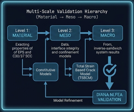 Multi-Scale Validation Hierarchy